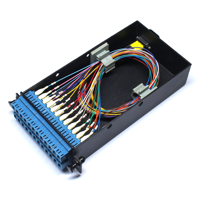
THE ULTIMATE LOW-LOSS MULTI-FIBER CONNECTIVITY CHOICE FOR 400G SYSTEM AND BEYOND

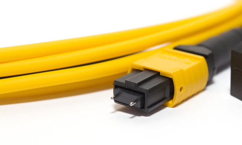
MPO connectors are well-suited for high-density, high-traffic applications including data centers and central offices. XFS' proprietary MPO manufacturing process employs the most advanced polishing technology for producing the MPO connectors with the best optical performance in the industry. We can offer 4, 8, 12, 24 and 48-fiber MPO assemblies, with ribbon, flat and round cable structure options. We can also provide MPO assemblies with IP (waterproof) connectivity.
OPTICAL PERFORMANCE
| Item | Parameter | Reference | |
|---|---|---|---|
| Standard 12c SM MPO | Standard 12c MM MPO | ||
| Insertion loss typ. | 0.1dB | 0.05dB | IEC 61300-3-4 |
| Insertion loss max. | 0.25dB | 0.15dB | |
| Return loss | APC: ≥65dB; UPC: ≥50dB | ≥35dB | IEC 61300-3-6 |
Other Suppliers
Use Standard MT Ferrules for Achieving IL max. as

FOR MM MPO

FOR SM MPO
XFS
Uses Standard MT Ferrules for Achieving IL max. as

FOR MM MPO

FOR SM MPO
WITH XFS’ HIGH-PRECISION, PROPRIETARY POLISHING TECHNOLOGY, WE CAN PRODUCE LOW-LOSS MPO WITHOUT USING LOW-LOSS MT FERRULE.
- Charles Sun, CEO
END-FACE GEOMETRY
12c MPO/MTP® Connector
| XFS | IEC 61755-3-31:2015 | |
|---|---|---|
| Minus Coplanarity (nm) | ≤200 | ≤400 |
| Ferrule Surface X-Angle (°) | -0.075 to +0.075 | -0.15 to +0.15 |
| Ferrule Surface Y-Angle (°) (SM) | 7.85 to 8.15 | 7.8 to 8.2 |
| Ferrule Surface Y-Angle (°) (MM) | -0.075 to +0.075 | -0.15 to +0.15 |
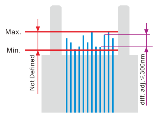
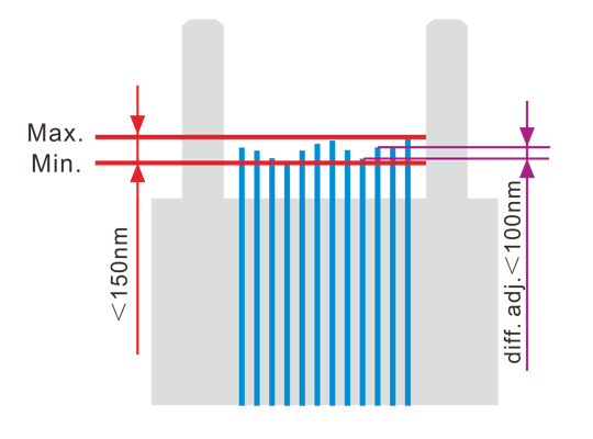
| Fiber Height (nm) | 1100 to 1500 | 1000 to 3500 |
| Fiber Differential Height-All (nm) | ≤150 | Not defined |
| Fiber Differential Height-Adj. (nm) | ≤100 | ≤300 |
| Fiber Tip Spherical Radius (mm) | ≥1 | ≥1 |
| Ferrule Surface X-Radius (mm) | ≥2000 | ≥2000 |
| Ferrule Surface Y-Radius (mm) | ≥50 | ≥5 |
| Core Dip (nm; for MM) | 0 to 100 | Not defined |
| Geometry Limit | ≤10 | ≤17.4 |
FIBER HEIGHT
Fiber Height is a critical factor for connection performance; it needs to be controlled within a certain range, and the distance between the shortest and the longest fiber as well as the variation in adjacent Fiber Heights have to be minimized to ensure good coplanarity of all fibers. XFS has set much tighter tolerances on Fiber Height than IEC to have the most consistent Fiber Heights for a perfect connection.
IEC 61755-3-31:2015
XFS
CORE DIP
Core Dip is major factor in determining insertion loss and return loss of multimode MPO connector. It is a recessed area of a fiber core located at the top of the fiber. Core Dip appears during polishing process because core is usually softer than cladding material and it is easier removed. Core Dip prevents proper physical contact and needs to be minimized. XFS’ MM MPO connector has less than one-third of Core Dip value than industry average.
Other suppliers

XFS

GEOMETRY LIMIT
Geometry Limit can be used to quantitatively assess the acceptability of an MPO’s end-face. This term is a calculated merit function, which relates X-slope angle, coplanarity, and fiber tip radii in comparison to the defined ferrule compression force. For a specific MPO’s end-face condition, lower calculated values for GL indicate a better geometry. XFS has set a far more strict GL than IEC to ensure its MPO connector has the best end-face geometry and optical performance.
IEC 61755-3-31:2015 (12c MPO)

XFS (12c MPO)

END-FACE QUALITY
For end-face quality, IEC guidelines allow a few defects that are small in size. XFS’ fiber optic connector is one of the very few in the industry to deliver connectors with zero defects on the ENTIRE FERRULE END FACE. Thus the connector’s light extraction efficiency is optimized.
| Zone | Range(μm) | XFS (MPO/APC) | IEC 61300-3-35 ed2.0 (APC) | ||
|---|---|---|---|---|---|
| Scratches | Defects | Scratches | Defects | ||
| A: Core | 0 to 25 | None | None | 4 ≤ 3μm | None |
| B: Cladding | 25 to 115 | None | None | No limit | No limit < 2μm 5 from 2μm to 5μm None > 5μm |
| Rest of ferrule | None | None | Not defined | Not defined | |


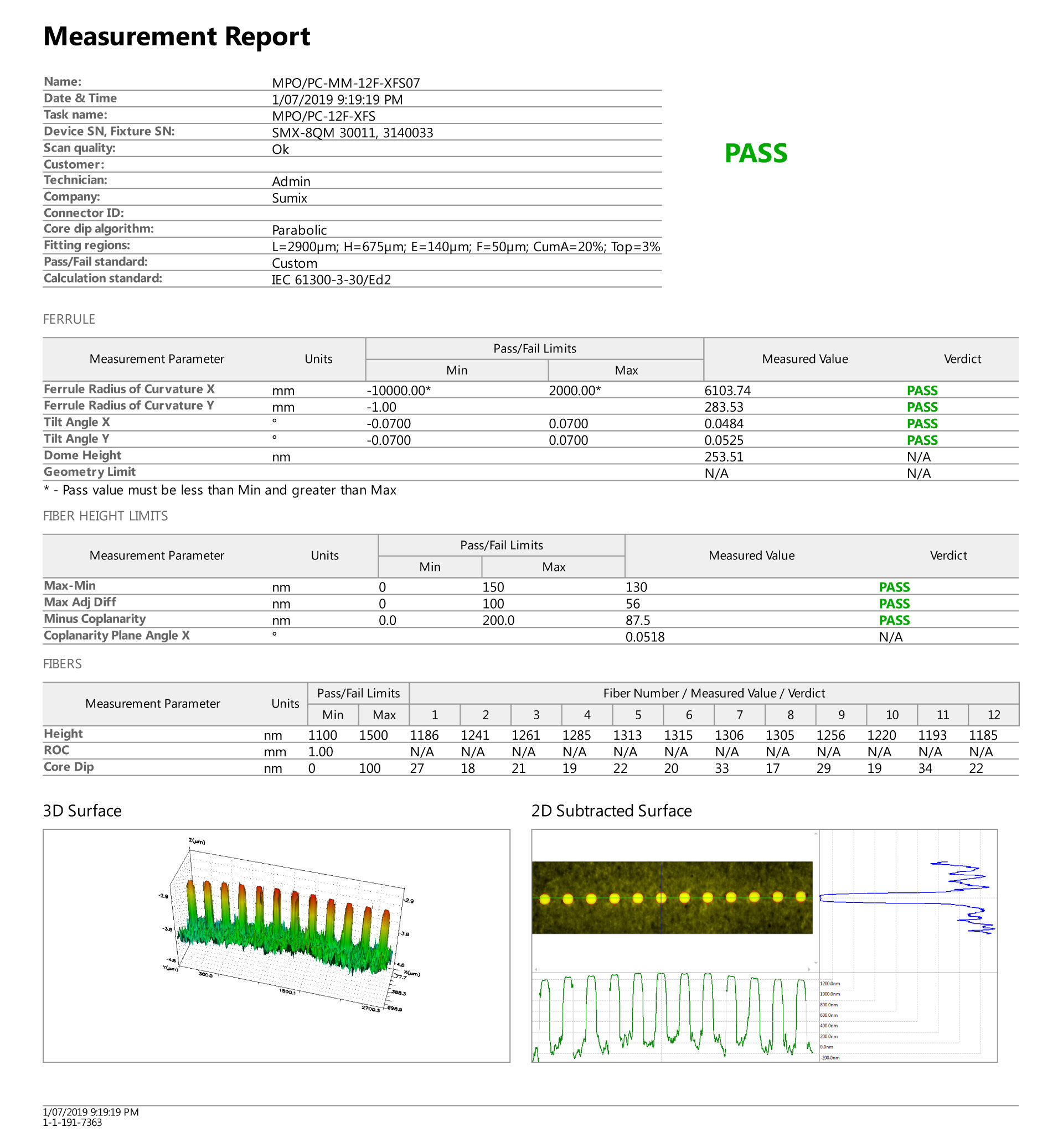
END-FACE GEOMETRY MEASUREMNT REPORT
3rd PARTY SPOT INSPECTION REPORT
‧ MPO-LC Fanouts
‧ LC/APC Jumpers
‧ SC/APC Jumpers
‧ LSH/APC Jumpers
PRODUCT PHOTOS
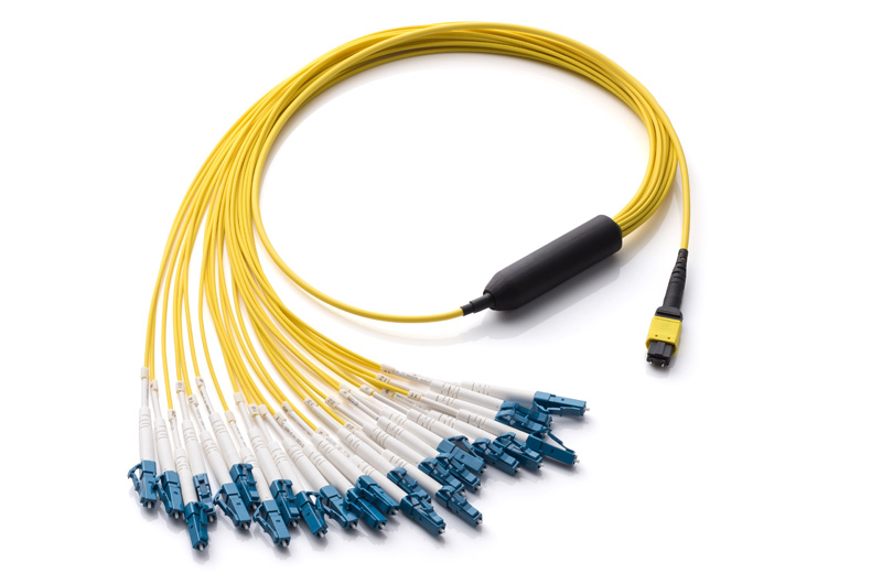
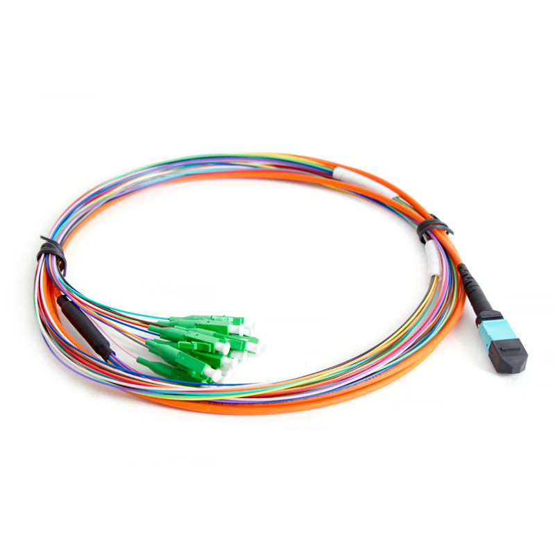
24c MPO/APC-LC/UPC Fanout
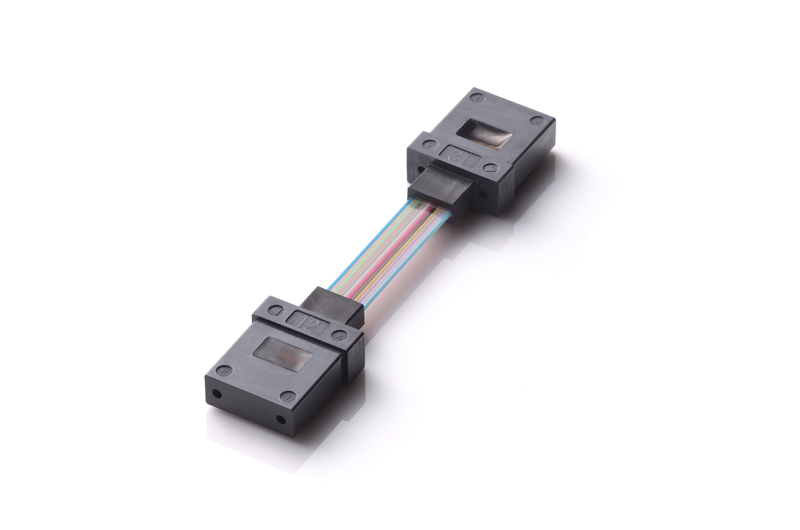
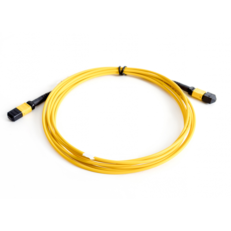
MT-MT Jumper
PRODUCT APPLICATIONS
 CENTRAL OFFICE
 FIBER TO THE BUILDING
 PON
PON DATA CENTER
 FIBER TO THE ANTENNA
 FIBER TO THE HOME
 FIBER IN THE HOME
 CATV
CATV BASE STATION
 WAN
WAN LAN
LAN SURVEILLANCE
 INDUSTRIAL
 HEALTHCARE
 AUTOMOTIVE
 DEFENSE


